2018-04-20: Making a Window Manager (part 1)
These are not the ICCCM protocols you’re looking for
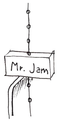
You know what happens in the office, usually late in the afternoon? That’s right! Exactly when you’re at the peak of productivity, Mr. Sun basically slams into your window and mocks you. In the face.
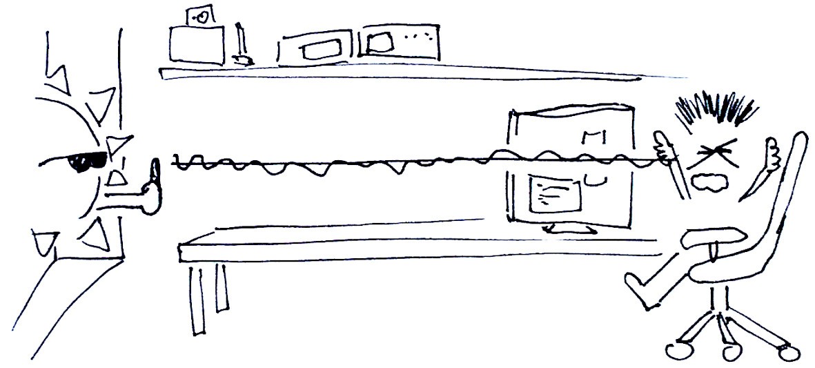
Artist’s depiction of the drama caused by sun’s ƒu-rays
You could raise from the chair and turn the shades, I guess. You could. But I can not. I need an automatic sun-b-gone mechanism! Something smart, IOT and with blockchain technology. A true Window Manager™.
Can we make it using only assorted junk found on the desk? Looking through the stuff I think I see a small stepper and some micros…
I believe We Can.
Sounds like the perfect project: approachable enough that you think you don’t need to plan ahead and silly enough that you don’t care about the results anyway. A nice weekend project, right?
I normally don’t write a lot (or at all), but thanks to a long train trip this article turned out to be way more detailed than anticipated. If you don’t want to read through, skip to the meat for the action-packed video.
A Dark Project
I have a single window in the side of the office. I’ll take daylight to crappy office lighting anytime, so I generally keep the shades completely open whenever possible. Unfortunately I get strong reflections from a building in the morning, and direct sunlight in the late afternoon.
I’d like to control the shades automatically using a motor, and turn them according to the current, actual lighting conditions. After-all, a simple time-based approach just wouldn’t cut it: first, it’s not smart (maybe clever at best), but second on a cloudy day the shades should stay open all the time!
Let’s check what’s available on the desk…
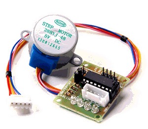
28BYJ-48 stepper motor with ULN2003A driver board
To move stuff I find this little stepper motor I had since I ordered my first Arduino kit years ago. It hasn’t that shiny NEMA look, and thus has never turned. It packs a decent torque for the size, thanks to a 64:1 reduction stage. This also results in 15 RPM only: if that’s enough for stirring soup then that’s enough for the shades too.
It could be driven higher with a different driver, but I don’t have anything readily available. Well, ready or not, 28BYJ-48, your time has come.
Brain-power will be provided by an Arduino Pro Mini. To add “AI” in your IOT product you need a Raspberry Pi according to latest trends, but for “smart” grade stuff this should be sufficient.
For light sensing I find some GL5528 photo-resistors. Imprecise and slow, but hey, I don’t need to receive signals from space here.
Light shaders
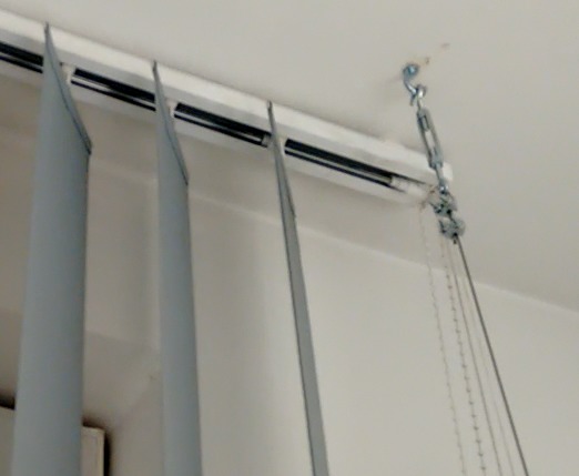
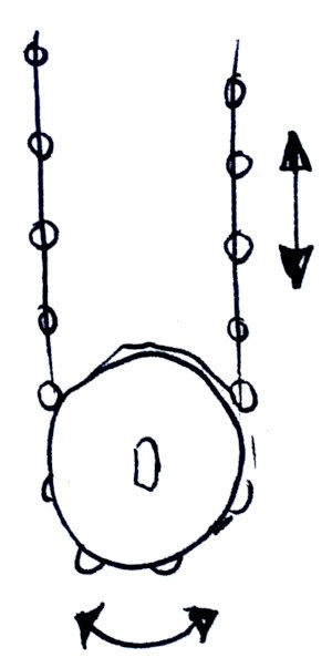
Tilting shades with rail mechanism
The shades I want to control are attached on the ceiling on a rail and have a tilting mechanism. Nothing fancy — it’s your average office shades. But sadly I’m not officially allowed to destroy or alter them irreversibly. Each mechanism has an independent string for control, so I’ll have to use that.
To maximize brightness in the office I generally keep the tilt stationary at 30-40 degrees (which I know blocks all direct sunlight in most cases), and just slide the shades on the rail.
Sliding is pretty quick. And the counter-weight on the string really seems to hint that is also the preferred way to control the shades.
Tilting on the other hand makes use of a string with little spherical beads for traction, which regularly gets tangled (no counterweight here) and turns the shades too slowly, usually requiring multiple arm strokes to get the job done.
Pulling strings
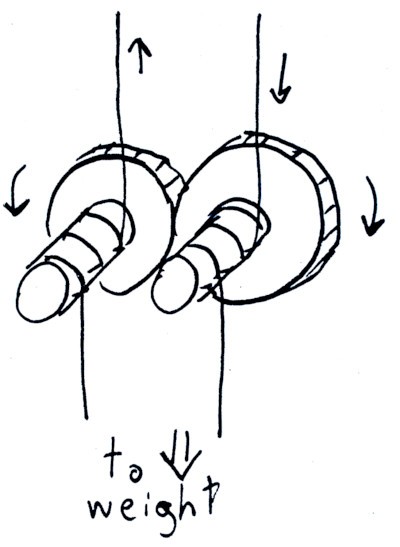
Pulling the shades’ string using counter-rotating worm gears
Instinctively, my first approach is to control the shades the same way I operate them, by “grabbing” on one end of the string for sliding. But it’s not as easy as it sounds. The string is thin and offers little grip. There’s also this counterweight at the end, which cannot be easily removed without breakage (it looks the two main halves have been glued permanently together to prevent my tampering).
A crazy concoction comes to mind: wrap the string on a worm gear, inline with a spur gear along the motor’s shaft. With the spur gear connected to a matching copy, we can have a second worm gear rotate in the opposite direction. By wrapping the second end of the string to it, the mechanism can pull down in both directions. You don’t need to cut the string or remove the counterweight: the wires are just coiled independently at each end. The grip is provided by the worm gear and the existing counterweight itself. A match made in heaven.
I pick a marker, turn the string around it a few times and test if I can pull it by just rotating the marker: works. So I take a dumb school-grade spring dynamometer I have at hand and check how much force I would need to pull the wire. Shockingly I discover it requires in excess of ~6N to move fully end-to-end. By “feel” it didn’t seem much, but it’s more than what I expected. When closing the shades only the first (furthermost) element is pulled on the rail. Each element pushes onto the next, increasing friction and weight at each stage. That, and a very crappy rail mechanism.
At 6N, and assuming a worm gear with a generous inner diameter of 1cm (to make it “3D printable” at a decent quality) we require no less than 30 N/mm of torque. The 28BYJ-48 with it’s ULN2003 driver I have is rated for about 34 N/mm. Add some friction for rotating the second gear and voilá: this thing will never step a single time.
You Fail Me right at the start, 28BYJ-48. If only you weren’t so slow already I could have added another reduction stage. The over-engineering of the combined solution would have been super-cool to show off.
Turning balls
Rotating the shades using a “ball” gear
Testing the string with the dynamometer refreshed the existence of tilting control in my mind, which I ignored at first. I pull this one instead, and I read about 2-2.5 N. It’s quite choppy, but requires a lot less force. We can work with this.
And it’s way simpler too, actually. Why didn’t I think of this first? If we put a gear with holes for the balls, we can directly pull in both directions with minimal tension, just like a timing belt.
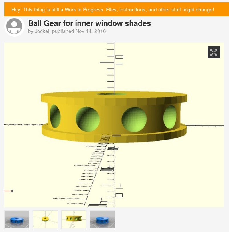
Working late I figured this sounds easy and must have already been done. I turn to Thingiverse. How would you search for a gear like that? “Sphere gear” returned mostly bearings. I tried “ball gear” and got a perfect hit.
The description even reads “for inner window shades” and comes with an OpenSCAD file! I skip the STL, open it with OpenSCAD and customize the gear in order to fit the motor shaft (DD type) and use the correct ball distance as measured.
I instantly print the model in PLA and test it out 15 minutes later. I just hold the motor in my hand with the gear inserted and slide it over the string. Aaaand it doesn’t work: the gear skips. The meshing looks good, but it doesn’t hold. If I increase the pull on the string it stops turning due to increased friction before it can reliably make a grip. Not good.
The fallacy here is thinking that you need a spherical slot for the beads to make traction. It’s as if I held a ruler on the side of the string and pulled down: unless you have a lot of tension, the spheres will slide out on the side. A good approach is to have a “comb”, U shaped, which has the diameter of the string. When the U comb catches a ball (or any other larger obstacle) it latches immediately and without escape. The shape/size of the ball is thus completely irrelevant.
The truth is that I should have searched for “bead gear” or “bead chain”, which didn’t occur to me until I started writing this. Thingiverse actually has at least some good designs that leverage this concept. But without this critical knowledge I decide to redesign the gear from scratch.
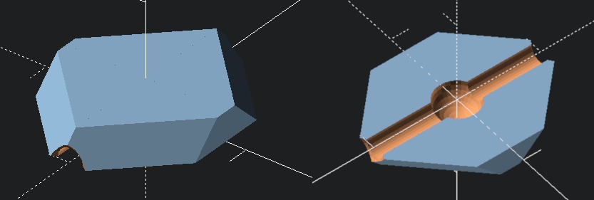
I cannot print a perfect U shape: the overhang needed (about 5mm) would have caused some defects on the inner part of the gear, even with supports. Splitting in two halves would be an option, but I’m lazy. The closest I can get is a ~60 degree overhang, so the gear becomes V grooved. The inner spacing is calculated exclusively based on the diameter of the string (2mm), while the thickness of the gear is the diameter of the beads plus some margin to close the edge on each side:
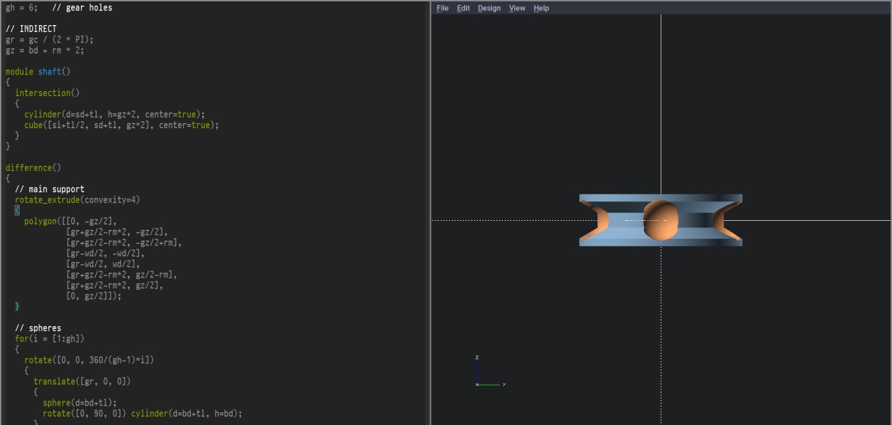
In the image above you can see that the bead is caught at the intersection of the “V” shape on 3 sides, which are constantly held at 90° once it has meshed with the bead chain. This way there is absolutely no tendency of the sphere to “pull out”: the bead sits suspended in the hole while rotating in the gear to avoid any outward tendency.
Another important detail is that the inner diameter of the gear cannot be chosen arbitrarily and must be a multiple of the distance between the beads of the chain. For perfect meshing I also subtract half the size of the string (causing the center of the sphere/string to land exactly at the required radius). The first gear I print has an outer diameter of only 20mm, with a rotation radius of 9mm. The smaller the better, as a smaller radius reduces the required torque. Recalculating, this results in 22.5 N/mm to pull, which we can satisfy with some margin to spare.
I’m quite confident at this point: I reprint the gear a few times until I get the tolerances on the shaft just right. The meshing is perfect, and the motor now pulls the string even if it’s completely loose. Time to move on to the support structure.
Call for support
I now need to define where everything goes before I can proceed. The motor needs to go at the end of the bead chain, along with it’s driver board, somehow affixed to the wall. The light sensor needs to go under the shelf directly above my desk in order to catch only direct light coming from the window and not from the overhead office lamp. Close to the sensor I also want a couple of switches (I’m thinking a triple throw switch) so I can have a manual override if needed. I’d like to minimize the control panel size, so I decide to put the Arduino close to the motor as well, making just a single bulky support for everything.
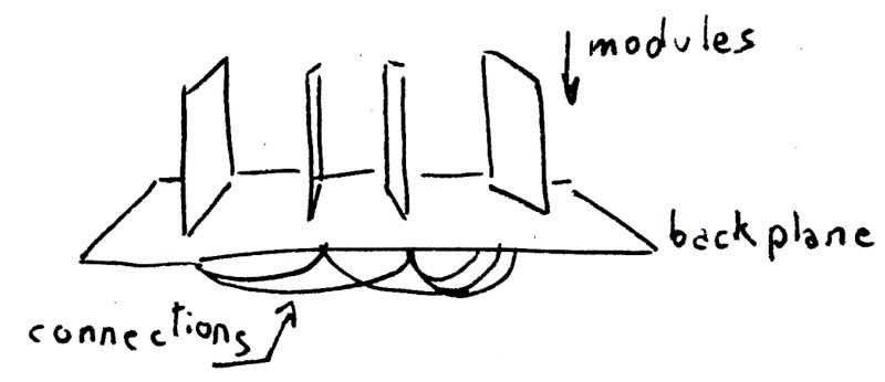
Boards with a support backplane
These “breakout boards”, including the stand-alone Arduino Mini, are always problematic to transform into a finished product. They might be great to fiddle, but how do you put the various required boards together? It’s always a mess. Most of those don’t even have mounting holes! Generally I solder them flat on an oversized perforated board to be used as support, but here it would be pretty wasteful.
A design I’ve used successfully in several project is to fix these boards vertically on a “backing plane”. If you use long angular headers you often can do this without making any additional support and save considerable space. The headers double for support and as a connection endpoint.
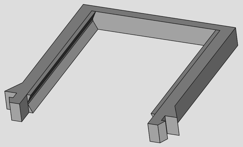
External board support clip with inset rails
I’ll use a variation on the same theme here, but in a vertical layout. I’ll just make an “L” shape support with one side sticking to the wall and the other (the “backing plane”) supporting the various boards and the motor perpendicularly.
I cannot solder the boards on plastic, but I can “clip” them to the backplane. Similar to hot-swap drives, I can make an U-shaped clip that goes over the entire board and snaps in the backplane with two teeth. To actually grab the board I just use a small inset rail.
These clips are very quick to print and thanks to the rigidity of PLA plastic they can hold a moderate weight in basically any direction. Another great advantage is that all you need is some holes on the baseplate. Oh, and you can remove them if needed!
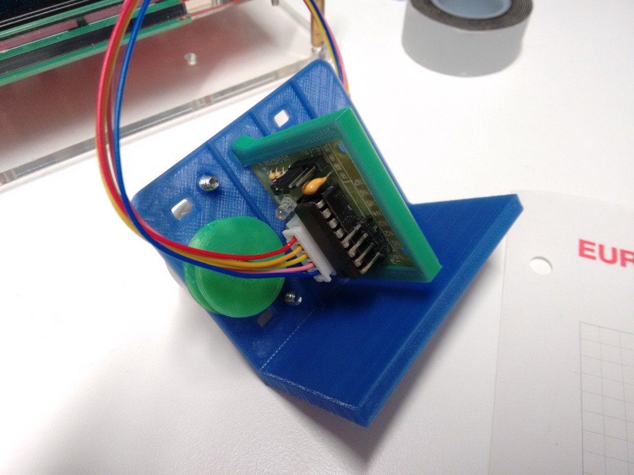
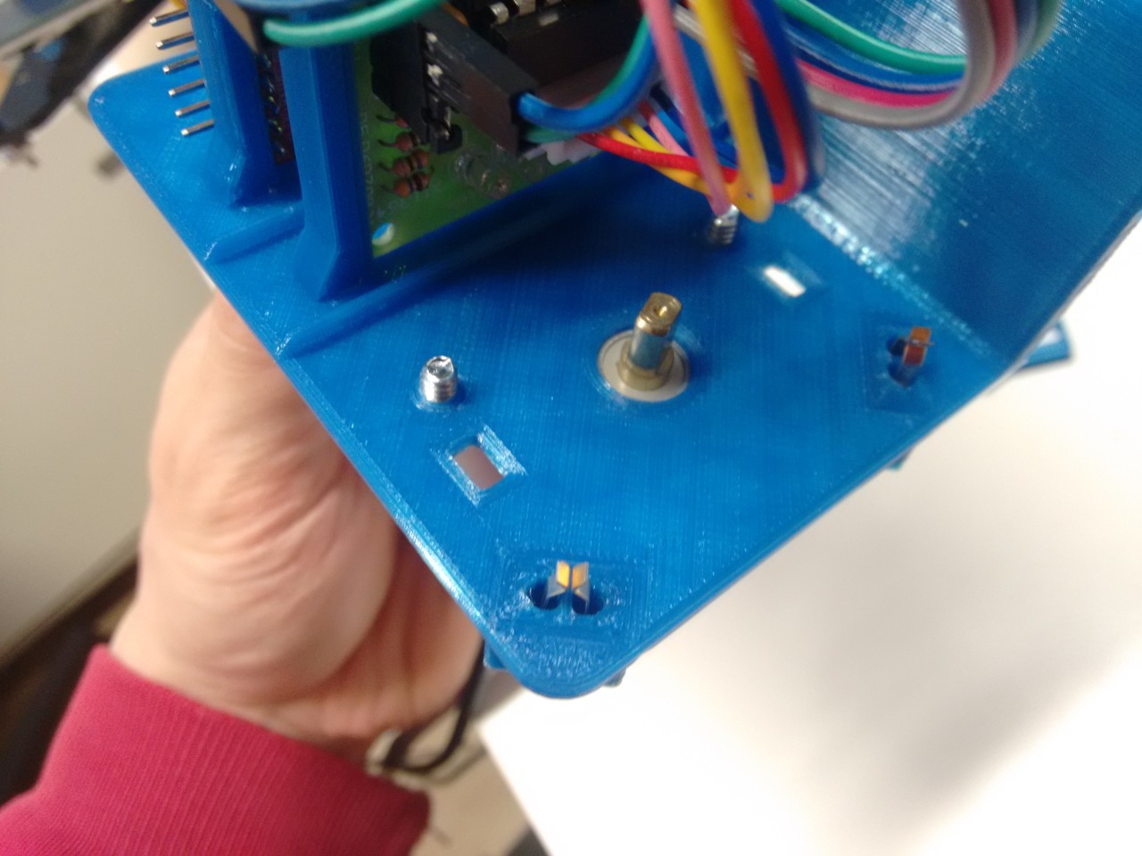
I make a first test print for checking how everything fits together. Cracking open FreeCAD I start to design the flat plane with the correct spacing for the motor shaft, mounting screws and the holes for the board clips. The length of the motor shaft limits the thickness of the plate to about 2mm, so I extrude for a total of 1.95mm (rounded to the closest printing layer height). I also print the first test clip for the driver board.
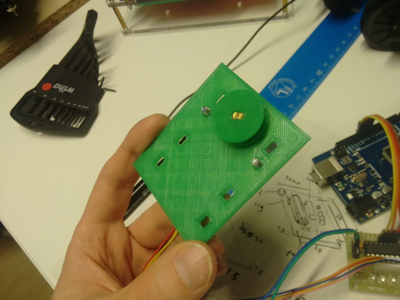
Baseplate prototype for assembly testing. Motor mounted on the back.
Everything fits rather well from the start. I used two random flat screws that I found in a drawer and simply force-fit the thread into the plastic. The driver board has enough clearance and sits in the rail without escaping. The only issue is that the whole support is a bit floppy on the edges, but it’s easily fixable.
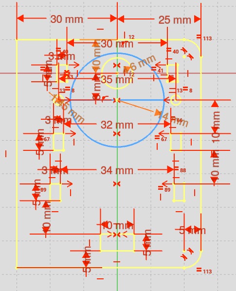
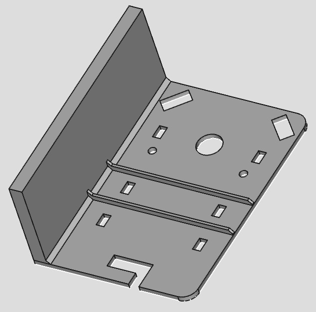
Parametric plane
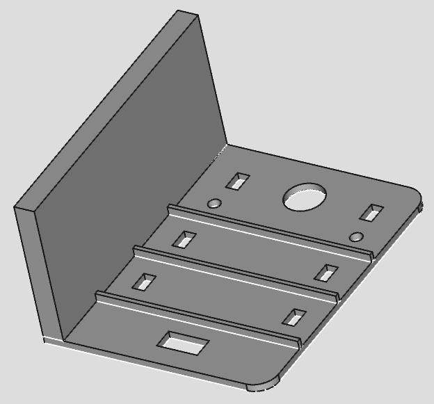
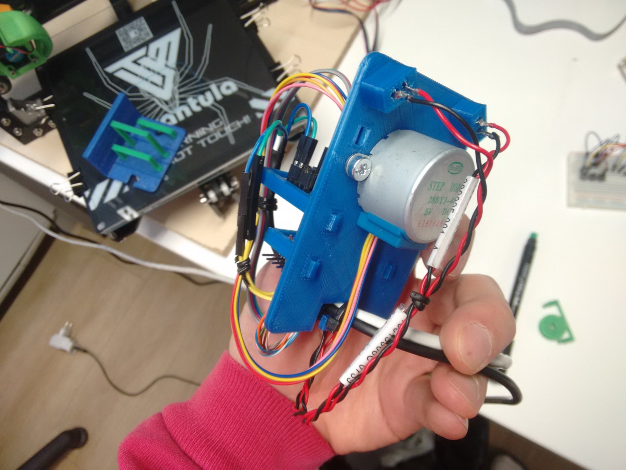
Reinforced support with wall mount
Printed support structure with clip
Back to FreeCAD to update the sketch. To complete the design I add three small reinforcement fins to increase stiffnes, one extra hole for the cable pass-through at the bottom (for stress relief) and the wall-mount side arm. My plan is to use some simple double-sided tape and affix the back side to the wall. Tape always fixes everything.
For power I cut the USB cable of a dead headset so I don’t have to solder the USB jack. Scrambling through the junk box an ethernet cable pops up. It has a fried plug but looks long enough so I cut the ends off and it becomes the carrier for the control panel.
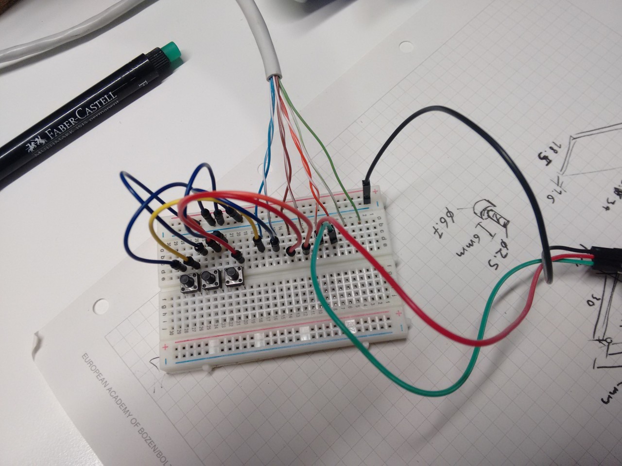
Before assembling everything I need to decide which pins I’m going to use and also have to program a basic control interface for the motor. For the control panel I use a couple of through-hole push buttons on a breadboard. Debugging anything with the mounted mechanism is going to be trickier, so doing that now is warranted.
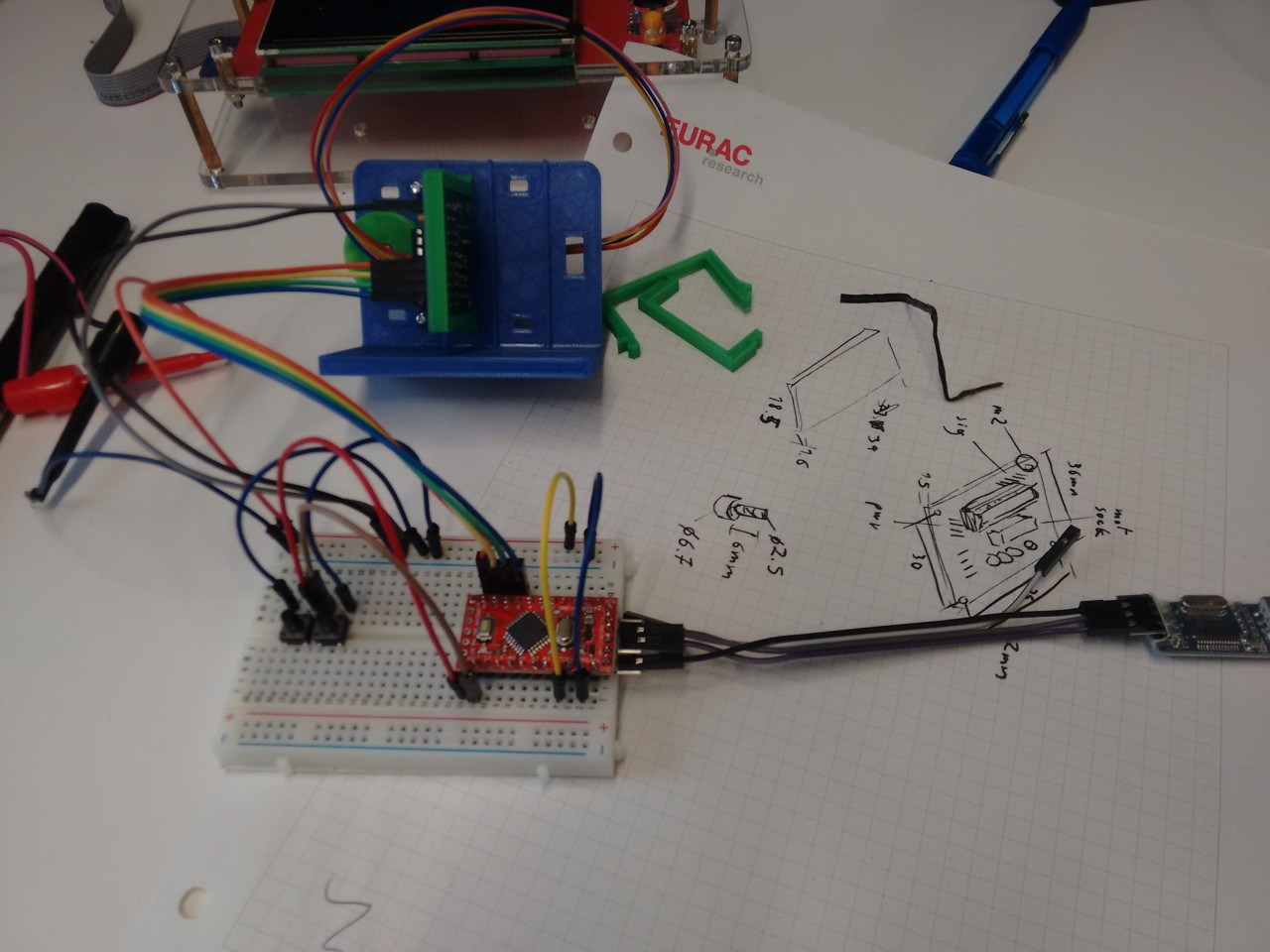
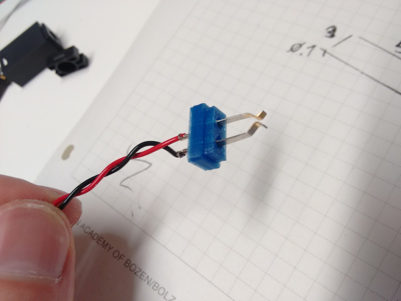
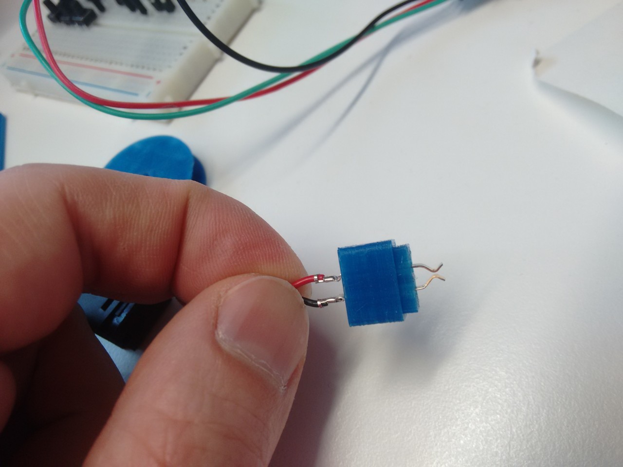
Flashing some firmware before wiring
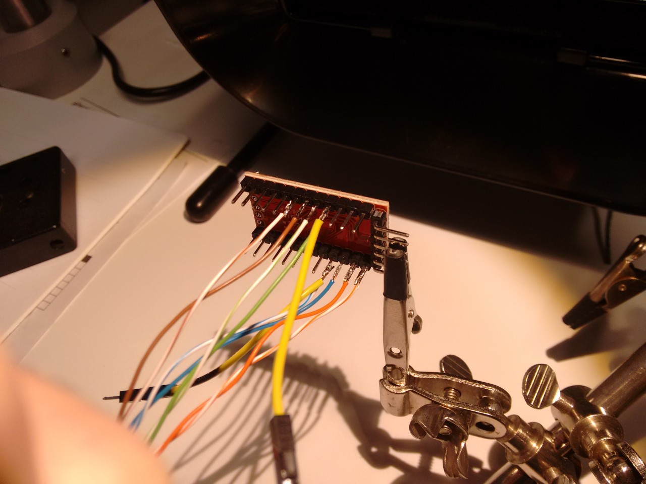
Wire connection reference image
For connecting I don’t want too spend much time with those painful dupont crimps. I butcher the Arduino and solder directly all the available conductors of the cable directly as I go. Mad, I know. You might think I’ve taken the above picture to document the progress, but it’s in fact my main reference image for the connections. For other board-to-board connections I already have short female jumpers.
While assembling the Arduino on the clip I already discover the first flaw of the support I printed earlier. The bottom pins of the Arduino touch the last reinforcement fin. This is what happens when working late after work over multiple days. Fortunately the clip is quite forgiving, and with some extra pressure it still clicks in. I might not sleep well at night, but nobody else will notice.
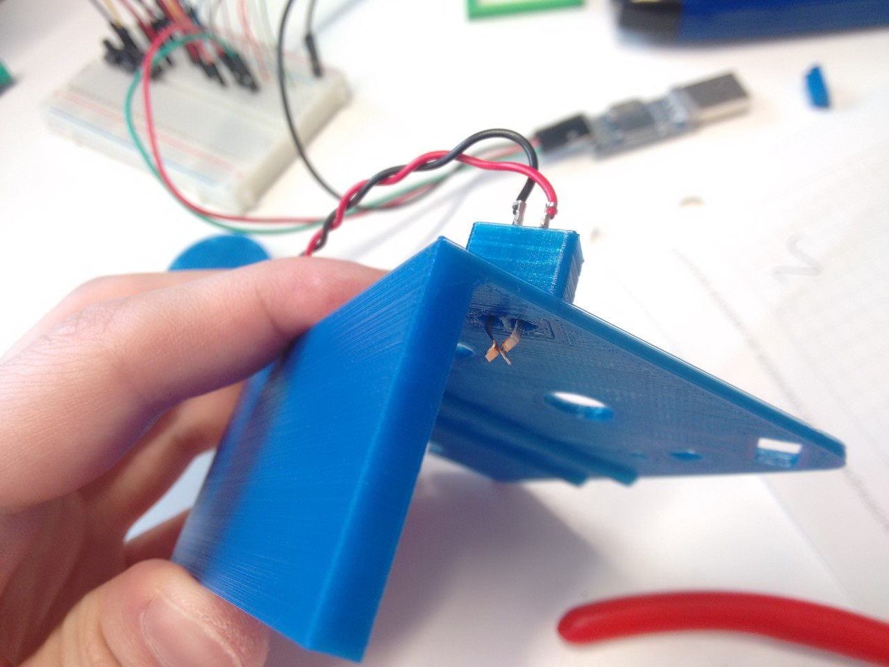
Assembly and test
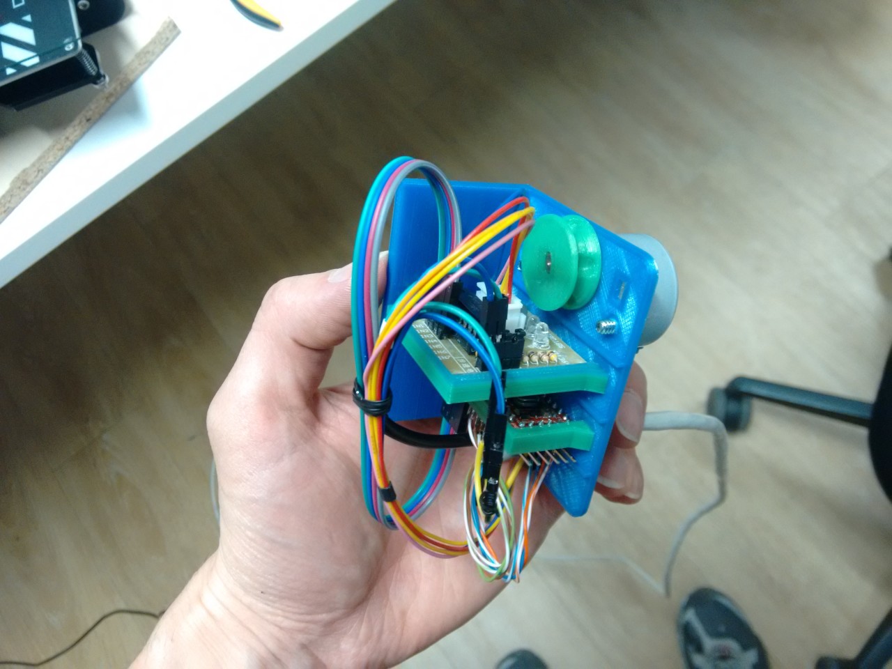
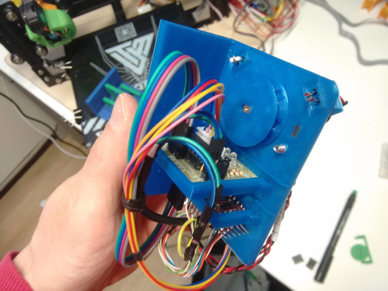
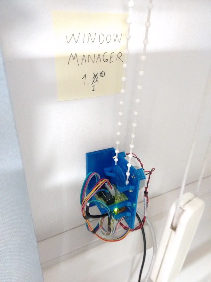
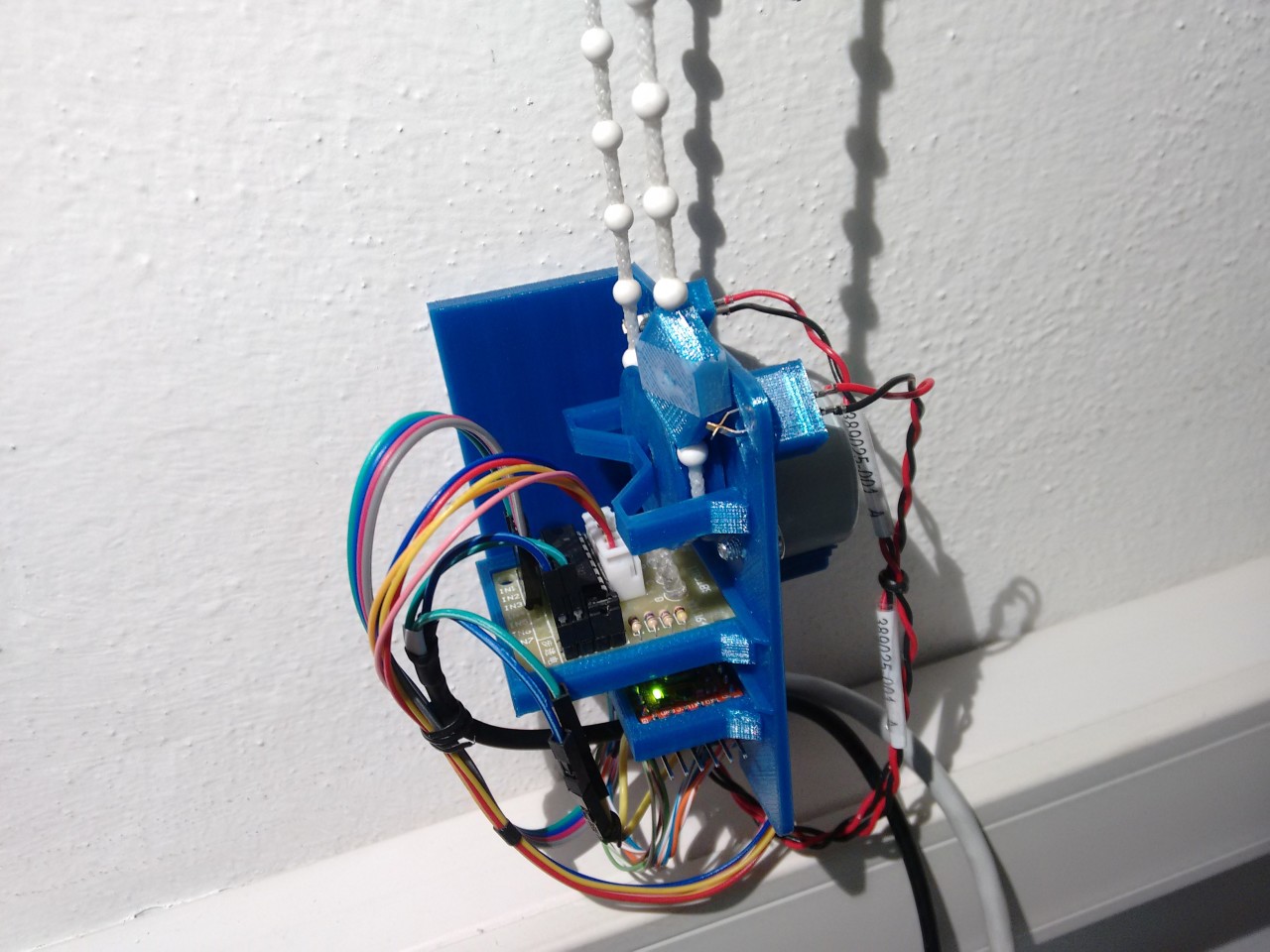
Assembled Window Manager 1.0
Preliminary control panel
You might notice there are two extra holes on the side of the gear: these are for an additional retention clip. It’s mounted as a last step, once the bead chain is inserted, to prevent the gear from ever falling off without fixing it permanently to the shaft.
The assembled support could be something you find in the set of a low-budget sci-fi movie. Looks complicated, and yet all it does is turn a gear. I love it. The filleted edges on the side are the icing on the cake: they really flaunt the care given by the engineer.
I lightly tin the ends on the other side of the cable and plug them on the breadboard for an impromptu control panel. With some coarse sand-paper I scratch the back of support and put the double-sided tape. Put the bead chain in the gear, the clip, and simply cram the whole block firmly on the wall. Time to push some buttons:
Next-day regrets
The mechanism is pretty slow, but it’s not as bad as it looks. In the video you see the motor performing a full 180° turn of the blinds, which is something that will never happen during normal usage.
I might need to rotate only 30-40 degrees at most from a perpendicular orientation. And with the light sensor, I’ll be doing that in small 5° steps which won’t take more than a few seconds.
The aim is a simple, pure feedback-based loop: at the beginning of the day, start opening and keep rotating until the brightness climbs. Stop when the brightness is beginning to decrease (meaning the blinds are perpendicular to the sensor). In normal operation, the motor would be idle while we peek at the light intensity periodically. When a threshold is hit (meaning we’re in direct sunlight), turn back a fixed amount of degrees and repeat until the brightness is back below the threshold.
Beautifully simple. Yet, how will it work in crappy weather, where the intensity of the office lights is greater than whatever comes out of the window? or.. during night? In these cases rotating the blinds won’t change the brighness, and thus tell us when to stop rotating. Knowing that the light intensity doesn’t change is also key to determine it’s dark/cloudy outside, but we should still reset the blinds to fully-open.
Starting from an unknown position we can reset the blinds to 0 degress by forcefully rotating in the same direction for 120°, eventually hitting the limit of the tilt mechanism itself, and just let the motor skip. From there, rotate back 90° to keep the blinds fully open.
It’s ugly, and most importantly, excruciatingly slow. Too slow for my taste. If we put an end-stop switch to detect the position of 0 and 90° though, the worst case scenario drops to 45° only, or about 30 seconds of time required.
Should have thought this through before. I now need to revise the support with two extra end-stop switches.
Blade runner
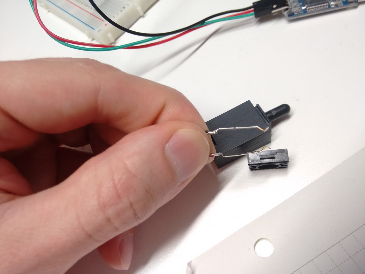
Case tamper-detection switch, cracked-open.
The easiest way to limit the excursion of the rotation is to put an obstacle in the bead chain itself, then place a microswitch close-by. When the obstacle hits the microswitch, stop rotating.
I cannot find any small microswitch though. Or any at all. Junk box to the rescue: there’s this tamper-detection switch that was recovered from a tower case that looks usable, but it’s a bit too big and the activation requires way too much force. I crack it open and find a pair of long switch blades, perfect to make a compact replacement.
Luckily I have several tamper switches, so I break another one, keep the springs for another project and start designing the blade support.
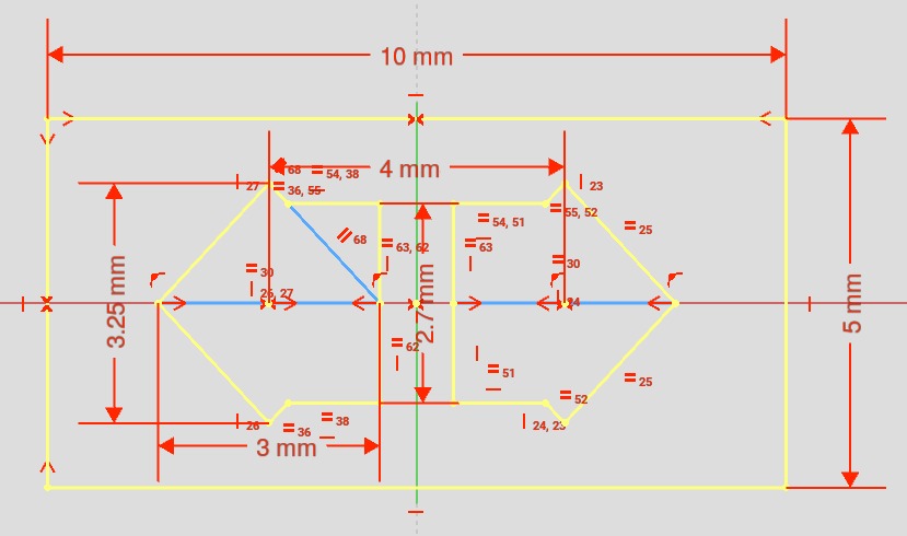
Each blade is 20mm in length, 2mm wide, with a convenient 3mm larger section at the base. By holding the wider base, we can let the tips flex freely.
Blade support plane
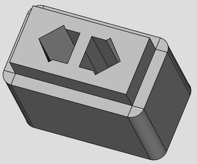
Recessed blade support structure
Blade support test print
To do this, I design a simple support with two square holes rotated by 45 degrees. The base of the blade simply jams inside vertically, squeezed by the side walls. To let the tips flex inwards we create a cavity in both holes towards the center, large enough to fit the rest of the blade without obstruction.
I decide to mount the entire switch directly on the base plate, making the switch blades stick out in the same way as the motor shaft. This way I can simply make another pair of holes in the plate and also adjust the height of the blades by simply offsetting the height of the support backwards. This design introduces some limitations for the end-stop, but we’ll discuss those later.
To verify the tolerances I complete a first test print which is only a few millimeters in height. The final height is calculated so that the narrow gap between the blades lines-up exactly at the center of the bead chain. This reduces the activation required force to a minimum, making the switch extremely sensible.
Finished end-stop switch
After the final switch is assembled we use a pair of small pliers to align and adjust the distance between the tips. The remaining space is about the same as the thickness of two sheets of paper.
Refined assembly
Revised baseplate
Assembled end-stop switch
Now that the size of the switches is known, it’s time to revise the support structure.
First, we correct our previous mistake by removing the last fin that was in the way and compensate by adding one extra layer of thickness to the base plate. The hole for the cable stress-relief also needs to be opened, as the board is now wired.
To increase the turning speed as much as possible I also decide to enlarge the size of the gear. But there’s not much margin: the mounting holes for the motor are in the way, and also there’s not much torque left available. The biggest size I can get is for 13 mm at the inner radius, a good 4 mm from the previous 9. This results in 32.5 N/mm of torque, just a smidge less than the rated maximum of 34 and hopefully also enough to squeeze the switch.
As for the position of the switches, I decide to put them at a 45° angle, offset outwards a full 5mm from the bead chain. This creates some margin to design a larger bead that can work by pressing both vertically and horizontally. Since the string tends to oscillate a lot while the motor is turning (look again at the video), I do not want the oscillations to cause a premature trigger by placing the switch too close.
I reprint all the parts, disassemble (or rather, break) the old support and migrate everything to the new:
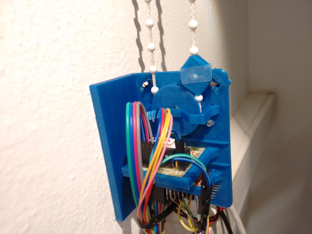
Revised support assembled, top view, no gear
In true sashimono-shi style, every component (except the motor *cough*) is snap-in, no glue needed, including the switches. See how tight the tolerances are? Hot Damn, I can recognize some serious end-stop porn when I see it.
Revised support assembled, back view
Revised support, top view, with gear
Each end-stop switch is connected to ground and a different GPIO pin in input-pullup mode, making it possible to distinguish each independently. Normally a single circuit would do for both, but here we have so many available pins we don’t have to complicate things further.
We also revise the gear retention clip slightly with an M shape in order to make it possible to insert and remove the bead chain in the empty spaces without removing the clip (a tricky business to do when the support is seated in the wall). To be fair though, the gear didn’t show any tendency to slide away from the shaft once the support is properly mounted.
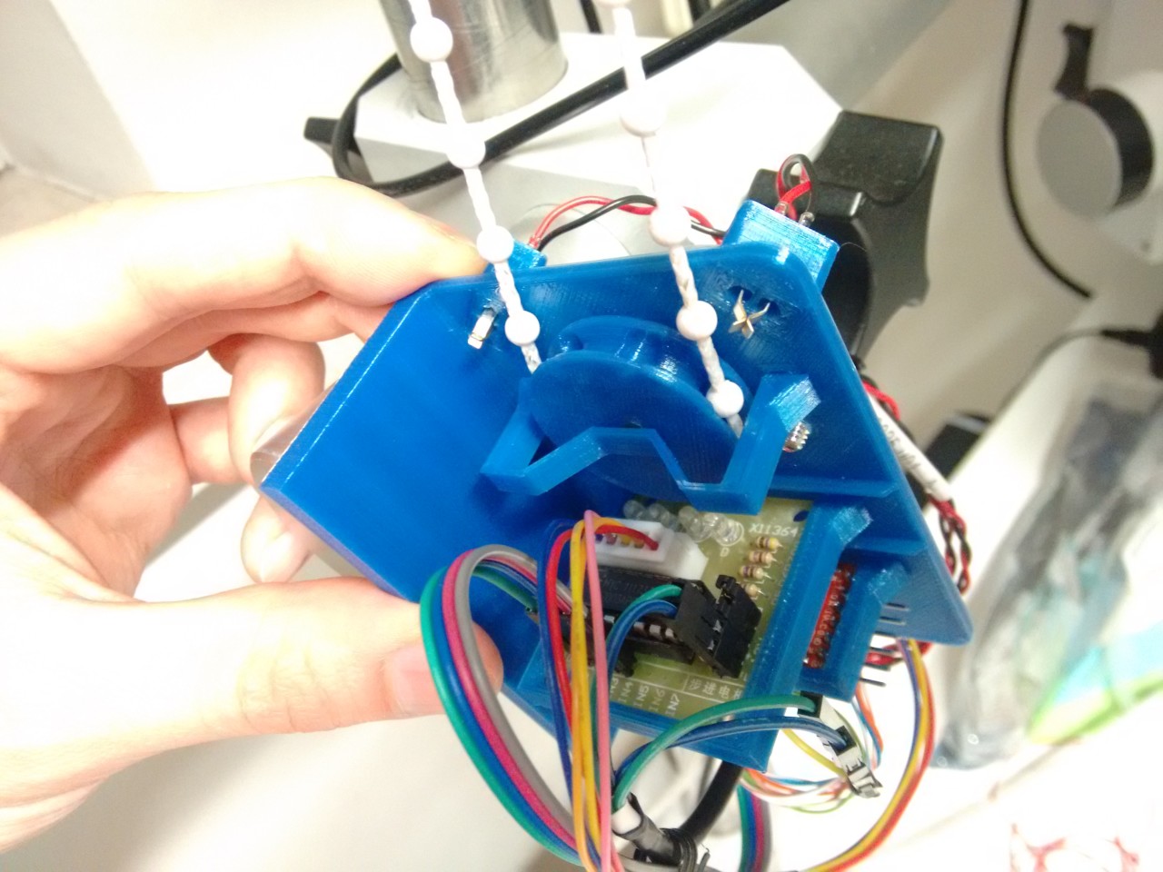
Assembled support with gear retention clip
Window Manager 1.1 mounted on the wall
Flip the switch: the Arduino still turns on and the motor can still pull it off! /me cleans some sweat from the brow. And I can now enjoy some ~40% speed-up thanks to the larger radius.
I reflash some code to test each end-switch, map them to some mnemonic and test them manually with my finger. Both work perfectly at the slightest touch.
Pierced beads
Perpendicular limiter jamming on the edge of the support
At this point, only the end-stop beads themselves are missing. You might think any shape large enough would do, like a big pill, but that’s definitely not the case!
Since we mounted the switches on the base of the support, lengthening it, the plane of the support itself is now in the way of any large obstruction going towards the switch blades.
The maximum thickness that can pass through is the same as the gear, or 7mm. And to press the switch, which is offset 5mm from the string, we need something as large as 10mm (5mm from each side).
You say bad design? I call it a nice challenge.
It’s obvious we need a rectangular shape, 7 by >10mm. The rectangle should sit exactly over the bead chain, so there must be a hole in the middle to let the string pass through. And since the end-stop must not move from the designated spot, we might as well take advantage of the beads and clamp one inside to avoid vertical movement.
But there’s a final catch: the string might (and will) rotate along it’s axis as the motor is turning. A simple rectangle, when turned perpendicular, will end up jamming on the edge of the support before touching the switch.
To solve this, we change the shape of the bead to a rhombus where each edge is cuneiform (ie: pointy). When an edge slams on the pointy side of the support, instead of being pushed outward, it will take on the path of least resistance and simply slide on a side. This causes the bead to rotate instead, aligning itself automatically to the plate.
The self-aligning end-stop bead as constructed via OpenSCAD
But wait! There’s more! The bead sits exactly in the middle between the gear and the blades. When it is being pulled by the gear it should first make contact with the switch. Shouldn’t this be case, the gear itself sits just 0.5mm below, pushing it outward towards the switch, increasing pressure until it does.
End-stop bead making contact, front view
First contact, side view
I reflash again the Arduino and add some trivial control logic for the end-stops. But a doubt arises: what happens if the switch is not activated and we just let the motor turn anyway?
Not much. Once the motor has squished the first blade of the switch (making contact), there’s simply not enough force left to move both of them outwards. Nothing gets damaged: it just stalls.
In fact I now almost fear the motor might skip a few steps during normal operation since it’s driven so close to the limit. To clear any doubt, I decide to test how reliable the entire system is.
I position the two beads relatively close to the support and write a small program to rock the chain back and forth, counting the steps before reaching each end-stop. This way I can do two things at once: ensure that motor hasn’t skipped before reaching the end-stop and verify that the switch is correctly activated each time, on both sides.
To detect any issue I simply dump some stats on the serial while it’s running. I let the system run for 200 iterations and go away for a stroll. When I come back the iterations are over and there has been a single skip, which is likely due the fact that I’m not doing any kind of de-bouncing on the switch.
I call myself lucky. I reposition the end-stop beads at their final position of 0 and 90° and happily go home.
The support is done.
Coming !soon
This article has been written a couple of weeks after actually doing the support board. That preliminary control panel? Still there, sitting on my desk. Before you’ll have the time to ask when it will be finally completed, let me finish with an imaginary Q/A session.
Mic to the first guy on the left
John: did you actually do this over a weekend?
Truth be told, this was done over several, long afternoon sessions after work, spanning about a week plus a rainy weekend. The guys showing these awesome single-weekend projects? All lies, I tell you! Don’t believe them. The printing time alone of the base support is in excess of 4 hours on this printer, which I ran overnight.
Rachel: do you always measure the forces involved?
I didn’t use to, until a couple designs I did in the past failed to work. I now mostly still don’t, unless I have a reason to believe I might be running close to the limit.
Thomas: what software did you use?
FreeCAD 0.17/beta mostly, with OpenSCAD to the rescue when a lot of boolean operations are involved such as the gear. Slic3r-PE for printing. Arduino-mk straight with gcc-avr for the code (no IDE). Everything was done on Linux.
Thomas: nice to see only OSS involved. Will you release the design files?
And deprive you of the learning experience and all the fun involved?
Second row, mic two please
Mike: so you blindly attached 3m of cable running from the Arduino to the control panel. How are you planning to wire the LDR…
I think we’re done here.
Thank you folks and see you next time for “part 2”; it has a been a nice train ride.